In the previous topic, Logic gates are the fundamental building blocks of digital integrated circuits. We listed 3 simple types of Logic Gates. Click here to read.
LOGIC GATE REPRESENTATION
They are commonly represented using these:
- Logic gate symbols
- Truth tables
- Logic equation
LOGIC GATE SYMBOLS
These symbols are:
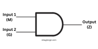
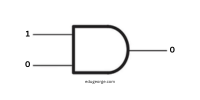
AND gate logic symbol:
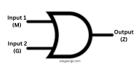
OR gate logic symbol:
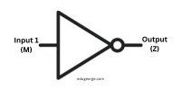
NOT gate logic symbol:
INPUT AND OUTPUT SIGNALS OF LOGIC GATES
Logic gates generate their signals, depending on the type of logic gate used.
Two common logic gate signals are:
- ON signal, which is represented by 1
- OFF signal, which is represented by 0
AND GATE LOGIC EXAMPLES:
-

If M = 1 and G = 1
M AND G = 1 * 1 = 1 -
If M = 1 and G = 0
M AND G = 1 * 0 = 0 -
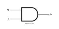
If M = 0 and G = 1
M AND G = 0 * 1 = 0 -
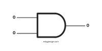
If M = 0 and G = 0
M AND G = 0 * 0 = 0
OR GATE LOGIC EXAMPLES:
-
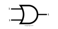
If M = 1 and G = 1
M OR G = 1 + 1 = 1 -
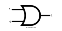
If M = 1 and G = 0
M OR G = 1 + 0 = 1 -
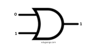
If M = 0 and G = 1
M OR G = 0 + 1 = 1 -
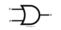
If M = 0 and G = 0
M OR G = 0 + 0 = 0
NOT GATE LOGIC EXAMPLES:
-

If M = 1
NOT M = 0 -
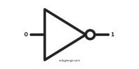
If M = 0
NOT M = 1
WHAT IS A TRUTH TABLE:
A truth table is a breakdown of a logic function by listing all possible values the function can attain.
These are the truth table for AND, OR and NOT logic gates:
TRUTH TABLE FOR LOGIC GATE ‘AND’
|
INPUT M |
INPUT G |
M AND G = OUTPUT Z |
|
0 |
0 |
0 |
|
0 |
1 |
0 |
| 1 | 0 |
0 |
| 1 | 1 |
1 |
TRUTH TABLE FOR LOGIC GATE ‘OR’
|
INPUT M |
INPUT G | M OR G = OUTPUT Z |
|
0 |
0 |
0 |
|
0 |
1 |
1 |
|
1 |
0 |
1 |
| 1 | 1 |
1 |
TRUTH TABLE FOR LOGIC GATE ‘NOT’
|
INPUT M |
~ M = OUTPUT Z |
|
0 |
1 |
| 1 |
0 |
LOGIC EQUATIONS
A logic equation is a mathematical statement that asserts the part of two expressions. The equation denoted as a linear expression of symbols that are normally separated into two sides that are joined by an equal sign.
Logic operations such as AND, OR and NOT have their respected symbols which are ^, v and ~. These are logic gate equations:
- LOGIC GATE ‘AND’:
M AND G = Z
OR
M ^ G = Z - LOGIC GATE ‘OR’:
M OR G = Z
OR
M v G = Z - LOGIC GATE ‘NOT’:
NOT M = Z
OR
~M = Z
USES OF LOGIC GATES
Logic gates are used for so many inventions such as:
- All digital electronic circuits are composed of logic gates. Without logic gates there would be no digital electronics.
- In FM (Frequency Modulation) transmitter, logic gates can be used for error checking. If the transmitter is off frequency, the logic gate can be used to inhabit the transmitter to stop inference.
- Logic is used for building a computer chip.
- It is used to make and control traffic light.